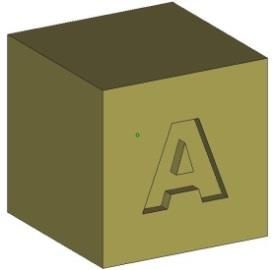
Text - Recessed
- Use a San Serif Font
- Arial is a good choice
- The font must have Bold applied
- Use a font size no smaller than 16 pt. (Yes, size matters. The larger the better)
- The font depth must be at least 0.8 mm deep (especially for smaller text – 16 pt.), larger text can be as shallow as 0.5 mm deep
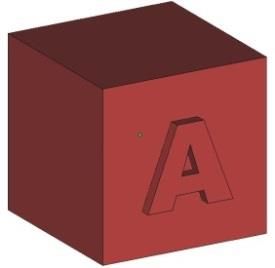
Text - Raised
- Use a San Serif Font
- Arial is a good choice
- The font must have Bold applied
- Use a font size no smaller than 14 pt. (the larger the better)
- The font height must be at least 0.6 mm high
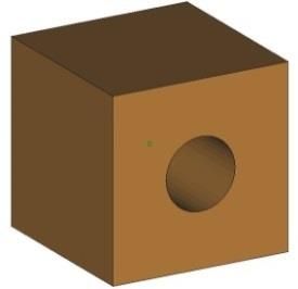
Holes
- At least 1.5 mm in diameter for vertical build orientation
- At least 2.0 mm in diameter for horizontal build orientation
- To maximize resolution, have the part built with the holes in vertical orientation and minimize part thickness in that area
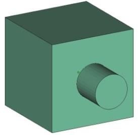
Pins
- Minimum diameter of 1.0 mm
- Either vertical or horizontal build orientation
- For moveable pins (including hinge pins) a minimum clearance of 0.3 mm per side (X-Y build) is required, a minimum of 0.5 mm per side (Z build) is required (this can be handled by a hole and/or pin diameter change)
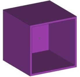
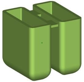
Thin Walls
- Our guaranteed minimum wall thickness for SLS is 1.0 mm (0.04 inches), anything less will be “best effort”
- Minimum wall thickness of 1.5 mm (0.06 inches) for reproducible measurements and mechanical properties
- Orient thin walls for plane by plane building to improve accuracy and resolvability
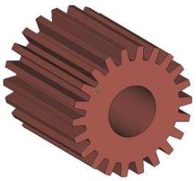
Gears
- Increase the shaft clearance to 1.0 mm (for free spinning gears)
- Increase the tooth separation distance to between 0.5 mm and 1.0 mm
- Note: Changes should be made to the model prior to the creation of the STL file
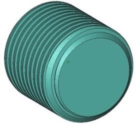
Threads
- Increase the thread clearance by a minimum of 0.1 mm (for printed threads)
- Have the threads added in a post-op process
- Note: Changes should be made to the model prior to the creation of the STL file
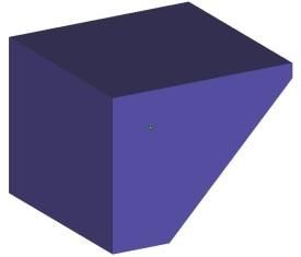
Feathered Edges
- Feathered, or knife edges, should taper to no less than 0.8mm (0.03 inches)
- DO NOT taper to a sharp edge (a sharp edge is fragile and easy to break)
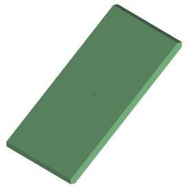
Large Flat Parts
- Large flat parts will warp – how much they warp depends on wall thickness, surrounding features, and overall part size
- Use a filled material to help minimize warping – (i.e. carbon filled) this will not eliminate warping but will greatly reduce warping
- Create a space-frame (grid) around the part(s) that is removed and sanded after receiving – this will not eliminate warping but will help reduce warping
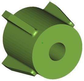
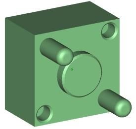
Bosses
- The outside diameter of the boss should be between 2X to 3X the diameter of the insert in order to provide sufficient strength and to minimize hoop shrink (shrink in the sidewall of the boss).
- The boss height should be equal to the height of the insert – if the boss is too tall shrinkage may occur below the level of the boss
- Ribs and gussets may be added for increased strength – rib or gusset thickness should be no greater than 60% of your boss sidewall thickness
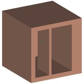
Wall Thickness
- The ideal wall thickness is between 1.5 mm and 3.0 mm (0.06 inches and 0.12 inches)
- Most important is to have a consistent wall thickness, try to keep all walls the same thickness avoiding extreme wall thickness variations – large blocks of material will cause excess heat and shrinkage resulting in part deformation
- Make any internal and/or external ribs, gussets or baffles no thicker than 60% of their adjoining wall thickness
Parts with Tight Tolerances
- Our standard production tolerances (with no post-op machining processes) are +/-0.25mm (+/-0.010 inches) for features less than or equal to 50mm in size, +/-0.38mm (+/-0.015 inches) for features that are greater than 50mm in size but less than or equal to 75mm in size. For features that are greater than 75mm in size our tolerance is +/-0.38mm plus 0.05mm per every 25mm over 75mm (+/-0.015 plus 0.002 inches per inch for each inch over 3.00 inches)
- Send a print, along with your RFQ, highlighting the important features and feature tolerances that are desired
- For the SLS process, it is only possible to build with symmetric tolerances
- For large quantity runs or large parts (with extreme tolerance requirements) leave extra material on the part that can then be removed thru a post-op machining process
- For small quantity runs (10 or less) send the CAD file (in a 3D CAD neutral format) along with your purchase request – this will allow us the ability to adjust the model in order to account for variations in shrink rates
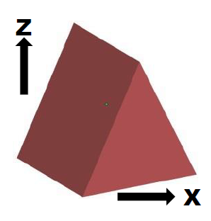
Build Orientation
- Our standard is to build all parts with the shortest side in the “Z” orientation
- If a particular build orientation is required, send a print along with your RFQ highlighting the desired “X-Y-Z” build orientation (be sure to specify the “Z” growth direction)
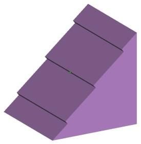
Layer Lines
- Since all parts are built layer by layer, angled and curved surfaces may have visible layer lines
- Build orientation can help minimize the visual appearance of layer lines – for a smoother surface request that the surface be printed (down) for build orientation
- Print the surface at 0 degrees (horizontal) or greater than 20 degrees
- A post-op process of tumbling and/or sanding can be used to smooth out layer lines
Living Hinge
- It is best to avoid using a living hinge in SLS if at all possible
- The best material for a living hinge is Nylon11 (PA850)
- The hinge should have a minimum thickness of 0.8 mm (0.03 inches)
- note this is below our minimum guaranteed build thickness of 1mm (0.04 inches) so this feature will be “best effort”
- Anneal the hinge prior to flexing – soak the part in boiling water for 10 minutes then allow the part to cool slowly (note: this could cause deformation and/or dimensional changes to other features on your part)
- Things to note:
- The hinge will flex, but do not expect it to flex like an injection molded hinge
- The hinge will only flex a few times before breaking
- If over flexed, the hinge will break
- The longer you can make the hinge the better chance you have of success